机器人仿真介绍
为什么需要机器人仿真
所谓机器人仿真其实就是通过软件来模仿硬件的特性,用于验证机器人算法、架构等。
原因在于:
-
仿真可以解决真机资源不足,真实的机器人一般价格都很贵,搭建起来也很耗费资源。
-
仿真可以保证环境的一致和稳定,举个例子,之前小鱼在部署导航系统时发现在A机器人上没问题,但在B机器人上老是丢位置,明明算法是一致的,后来发现是B机器人的IMU模块出现了松动。
-
仿真场景可以更加灵活,在测试机器人算法时可以通过仿真软件快速更改仿真环境,验证算法(甚至还可以让机器人原地起飞)
仿真有哪些缺点
之前听一位做机械臂动力学的朋友说,他们做研发时候从来没做过仿真,原因在于仿真环境中的机器人和真实环境机器人差别过大。
所以机器人仿真的主要缺陷就是仿真不全,现实世界中的环境非常复杂,光线、材质、电磁干扰等等,仿真平台无法做到100%的仿真。
常用仿真平台
Gazebo
Gazebo是ROS中常用的机器人仿真平台,也是OSRF(开源机器人基金会)的作品之一
WeBots
Webots由Cyberbotics公司开发,是一个用于模拟机器人的开源和多平台桌面应用程序。它提供了一个完整的开发环境来对机器人进行建模、编程和仿真。Webots内核基于开源动力学引擎ODE和OpenGL,可以在Windows,Linux和macOS上运行,并且支持多种编程语言(C/C++,Python,Java,MATLAB)。
Ignition
官网链接:https://gazebosim.org/ 官方文档:https://ignitionrobotics.org/docs
Ignition是继承于Gazebo的下一代仿真平台,Ignition Robotics基于开发库和云服务等丰富全面的工具箱,提供了一种全新的仿真方式,进一步简化仿真。高度逼真的传感器可在接近真实的环境中快速迭代更新机器人物理设计。在安全上可测试控制策略,并在持续的集成化侧重中利用仿真的诸多优势。
Unity
官网链接:hhttps://unity.com/ UnityForROS2:https://github.com/RobotecAI/ros2-for-unity
Unity Robotics软件包带有许多现成的接口,能让你轻松与ROS或ROS 2的交换信息。你也能用URDF Importer直接从URDF文件中导入机器人配置,在Unity高质量的渲染管线与高精度的物理模拟加持下开始训练机器人。Unity的Asset Store还售有大量现成的环境和道具,可用于补充机器人的训练环境、完善训练任务。只需几键,你搭建的模拟就可以构建并部署到Windows 10、Mac OS或Linux等任意主流操作系统。你甚至可以使用C#、Bolt可视化编程及Asset Store上的众多脚本和实用程序来根据自己的需求进一步定制模拟环境。
为机器人URDF模型注入物理属性
机器人仿真就是用软件来模拟硬件的特性,那么我们必须要告诉仿真平台机器人各个关节的物理属性,比如:
- 有多重
- 有多大的惯性
- 重心在哪
- 碰撞边界在哪
- 关节的上下界限
- 其他的一些必要信息等等
需要哪些物理信息?
一般来说有碰撞和内参两个就够了,但是因为之前的偷懒,还要加一个摩擦力配置。
碰撞描述是物体的用于碰撞检测的包围形状。内参用于描述物体的质量,惯性矩阵。link的摩擦力。
碰撞检测
在机器人仿真中,我们要对物体之前是否接触,是否发生碰撞做检测,常用的检测方法比如包围盒,判断两个物体的包围盒是否相交来快速判断物体是否发生碰撞。
在URDF中,我们可以在link标签下添加collison子标签来对物体的形状进行描述。
collision可以包含的子标签如下:
- origin,表示碰撞体的中心位姿
- geometry,用于表示用于碰撞检测的几何形状
- material,可选的,描述碰撞几何体的材料(这个设置可以在gazebo仿真时通过view选项看到碰撞包围体的形状)
一个完整的collision标签实例如下:
    <collision>
      <origin xyz="0 0 0.0" rpy="0 0 0"/>
      <geometry>
        <cylinder length="0.12" radius="0.10"/>
      </geometry>
      <material name="blue">
          <color rgba="0.1 0.1 1.0 0.5" />
      </material>
    </collision>
旋转惯量
旋转惯量矩阵是用于描述物体的惯性的,在做动力学仿真的时候,这些参数尤为重要。
在URDF中我们可以通过在link下添加inertial子标签,为link添加惯性参数的描述。
intertial标签包含的子标签如下:
- mass,描述link的质量
- inertia,描述link的旋转惯量(该标签有六个属性值ixx\ixy\ixz\iyy\iyz\izz)
一个完整的inertial标签示例如下:
   <inertial>
      <mass value="0.2"/>
      <inertia ixx="0.0122666" ixy="0" ixz="0" iyy="0.0122666" iyz="0" izz="0.02"/>
    </inertial>
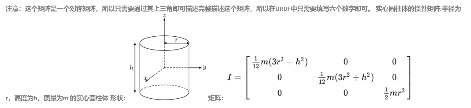
关于intertial的属性设置,不是随意设置的,常见的几何体我们可以通过公式进行计算。
比如我们上一章节的fishbot的轮子和车体,都是实心圆柱,可以采用下面的公式进行计算:
摩擦力和刚性系数
在Fishbot的URDF中,前面的支撑轮主要起支撑作用,因为我们将其使用fixed标签固定到了base_link上,所以它无法转动。
哪该怎么办呢?我们可以要把这个轮子的摩擦力设置为0,让它直接在地上滑动即可,
如何设置呢?6行代码放到URDF中:
  <gazebo reference="caster_link">
    <mu1 value="0.0"/>
    <mu2 value="0.0"/>
    <kp value="1000000.0" />
    <kd value="10.0" />
  </gazebo>
其中mu1,mu2代表摩擦力,kp,kd代表刚性系数。
为FishBot添加物理惯性
利用上面的方法公式,为我们的fishbot的link添加好物理属性,完成后的base_link如下:
  <!-- base link -->
  <link name="base_link">
      <visual>
      <origin xyz="0 0 0.0" rpy="0 0 0"/>
      <geometry>
        <cylinder length="0.12" radius="0.10"/>
      </geometry>
      <material name="blue">
          <color rgba="0.1 0.1 1.0 0.5" />
      </material>
    </visual>
    <collision>
      <origin xyz="0 0 0.0" rpy="0 0 0"/>
      <geometry>
        <cylinder length="0.12" radius="0.10"/>
      </geometry>
      <material name="blue">
          <color rgba="0.1 0.1 1.0 0.5" />
      </material>
    </collision>
    <inertial>
      <mass value="0.2"/>
      <inertia ixx="0.0122666" ixy="0" ixz="0" iyy="0.0122666" iyz="0" izz="0.02"/>
    </inertial>
  </link>
完全添加好的机器人URDF模型:
<?xml version="1.0"?>
<robot name="fishbot">


  <!-- Robot Footprint -->
  <link name="base_footprint"/>

  <joint name="base_joint" type="fixed">
    <parent link="base_footprint"/>
    <child link="base_link"/>
    <origin xyz="0.0 0.0 0.076" rpy="0 0 0"/>
  </joint>


  <!-- base link -->
  <link name="base_link">
  	<visual>
      <origin xyz="0 0 0.0" rpy="0 0 0"/>
      <geometry>
		<cylinder length="0.12" radius="0.10"/>
      </geometry>
      <material name="blue">
      	<color rgba="0.1 0.1 1.0 0.5" />
      </material>
    </visual>
    <collision>
      <origin xyz="0 0 0.0" rpy="0 0 0"/>
      <geometry>
		<cylinder length="0.12" radius="0.10"/>
      </geometry>
      <material name="blue">
      	<color rgba="0.1 0.1 1.0 0.5" />
      </material>
    </collision>
    <inertial>
      <mass value="0.2"/>
      <inertia ixx="0.0122666" ixy="0" ixz="0" iyy="0.0122666" iyz="0" izz="0.02"/>
    </inertial>
  </link>

  <!-- laser link -->
  <link name="laser_link">
    <visual>
      <origin xyz="0 0 0" rpy="0 0 0"/>
      <geometry>
        <cylinder length="0.02" radius="0.02"/>
      </geometry>
      <material name="black">
        <color rgba="0.0 0.0 0.0 0.5" />
      </material>
    </visual>
    <collision>
      <origin xyz="0 0 0" rpy="0 0 0"/>
      <geometry>
        <cylinder length="0.02" radius="0.02"/>
      </geometry>
      <material name="black">
        <color rgba="0.0 0.0 0.0 0.5" />
      </material>
    </collision>
    <inertial>
    <mass value="0.1"/>
      <inertia ixx="0.000190416666667" ixy="0" ixz="0" iyy="0.0001904" iyz="0" izz="0.00036"/>
    </inertial>
  </link>

  <!-- laser joint -->
  <joint name="laser_joint" type="fixed">
      <parent link="base_link" />
      <child link="laser_link" />
      <origin xyz="0 0 0.075" />
  </joint>

  <link name="imu_link">
  	<visual>
      <origin xyz="0 0 0.0" rpy="0 0 0"/>
      <geometry>
		    <box size="0.02 0.02 0.02"/>
      </geometry>
    </visual>
    <collision>
      <origin xyz="0 0 0.0" rpy="0 0 0"/>
      <geometry>
		    <box size="0.02 0.02 0.02"/>
      </geometry>
    </collision>
    <inertial>
      <mass value="0.1"/>
        <inertia ixx="0.000190416666667" ixy="0" ixz="0" iyy="0.0001904" iyz="0" izz="0.00036"/>
      </inertial>
  </link>

  <!-- imu joint -->
  <joint name="imu_joint" type="fixed">
      <parent link="base_link" />
      <child link="imu_link" />
      <origin xyz="0 0 0.02" />
  </joint>


  <link name="left_wheel_link">
      <visual>
        <origin xyz="0 0 0" rpy="1.57079 0 0"/>
        <geometry>
          <cylinder length="0.04" radius="0.032"/>
        </geometry>
          <material name="black">
            <color rgba="0.0 0.0 0.0 0.5" />
          </material>
      </visual>
      <collision>
        <origin xyz="0 0 0" rpy="1.57079 0 0"/>
        <geometry>
          <cylinder length="0.04" radius="0.032"/>
        </geometry>
          <material name="black">
            <color rgba="0.0 0.0 0.0 0.5" />
          </material>
      </collision>
      <inertial>
        <mass value="0.2"/>
          <inertia ixx="0.000190416666667" ixy="0" ixz="0" iyy="0.0001904" iyz="0" izz="0.00036"/>
        </inertial>
  </link>

  <link name="right_wheel_link">
      <visual>
        <origin xyz="0 0 0" rpy="1.57079 0 0"/>
        <geometry>
          <cylinder length="0.04" radius="0.032"/>
        </geometry>
          <material name="black">
            <color rgba="0.0 0.0 0.0 0.5" />
          </material>
      </visual>
      <collision>
        <origin xyz="0 0 0" rpy="1.57079 0 0"/>
        <geometry>
          <cylinder length="0.04" radius="0.032"/>
        </geometry>
          <material name="black">
            <color rgba="0.0 0.0 0.0 0.5" />
          </material>
      </collision>
      <inertial>
      <mass value="0.2"/>
      <inertia ixx="0.000190416666667" ixy="0" ixz="0" iyy="0.0001904" iyz="0" izz="0.00036"/>
    </inertial>
  </link>

  <joint name="left_wheel_joint" type="continuous">
      <parent link="base_link" />
      <child link="left_wheel_link" />
      <origin xyz="-0.02 0.10 -0.06" />
      <axis xyz="0 1 0" />
  </joint>

  <joint name="right_wheel_joint" type="continuous">
      <parent link="base_link" />
      <child link="right_wheel_link" />
      <origin xyz="-0.02 -0.10 -0.06" />
      <axis xyz="0 1 0" />
  </joint>

  <link name="caster_link">
      <visual>
        <origin xyz="0 0 0" rpy="1.57079 0 0"/>
        <geometry>
            <sphere radius="0.016"/>
        </geometry>
          <material name="black">
            <color rgba="0.0 0.0 0.0 0.5" />
          </material>
      </visual>
      <collision>
        <origin xyz="0 0 0" rpy="1.57079 0 0"/>
        <geometry>
            <sphere radius="0.016"/>
        </geometry>
          <material name="black">
            <color rgba="0.0 0.0 0.0 0.5" />
          </material>
      </collision>
      <inertial>
      <mass value="0.02"/>
      <inertia ixx="0.000190416666667" ixy="0" ixz="0" iyy="0.0001904" iyz="0" izz="0.00036"/>
    </inertial>
  </link>

  <joint name="caster_joint" type="fixed">
      <parent link="base_link" />
      <child link="caster_link" />
      <origin xyz="0.06 0.0 -0.076" />
      <axis xyz="0 1 0" />
  </joint>


  <gazebo reference="caster_link">
    <material>Gazebo/Black</material>
  </gazebo>

  <gazebo reference="caster_link">
    <mu1 value="0.0"/>
    <mu2 value="0.0"/>
    <kp value="1000000.0" />
    <kd value="10.0" />
    <!-- <fdir1 value="0 0 1"/> -->
  </gazebo>


  <gazebo>
    <plugin name='diff_drive' filename='libgazebo_ros_diff_drive.so'>
          <ros>
            <namespace>/</namespace>
            <remapping>cmd_vel:=cmd_vel</remapping>
            <remapping>odom:=odom</remapping>
          </ros>
          <update_rate>30</update_rate>
          <!-- wheels -->
          <!-- <left_joint>left_wheel_joint</left_joint> -->
          <!-- <right_joint>right_wheel_joint</right_joint> -->
          <left_joint>left_wheel_joint</left_joint>
          <right_joint>right_wheel_joint</right_joint>
          <!-- kinematics -->
          <wheel_separation>0.2</wheel_separation>
          <wheel_diameter>0.065</wheel_diameter>
          <!-- limits -->
          <max_wheel_torque>20</max_wheel_torque>
          <max_wheel_acceleration>1.0</max_wheel_acceleration>
          <!-- output -->
          <publish_odom>true</publish_odom>
          <publish_odom_tf>true</publish_odom_tf>
          <publish_wheel_tf>false</publish_wheel_tf>
          <odometry_frame>odom</odometry_frame>
          <robot_base_frame>base_footprint</robot_base_frame>
      </plugin>


      <plugin name="fishbot_joint_state" filename="libgazebo_ros_joint_state_publisher.so">
        <ros>
          <remapping>~/out:=joint_states</remapping>
        </ros>
        <update_rate>30</update_rate>
        <joint_name>right_wheel_joint</joint_name>
        <joint_name>left_wheel_joint</joint_name>
      </plugin>
      </gazebo>

      <gazebo reference="laser_link">
        <material>Gazebo/Black</material>
      </gazebo>

    <gazebo reference="imu_link">
      <sensor name="imu_sensor" type="imu">
      <plugin filename="libgazebo_ros_imu_sensor.so" name="imu_plugin">
          <ros>
            <namespace>/</namespace>
            <remapping>~/out:=imu</remapping>
          </ros>
          <initial_orientation_as_reference>false</initial_orientation_as_reference>
        </plugin>
        <always_on>true</always_on>
        <update_rate>100</update_rate>
        <visualize>true</visualize>
        <imu>
          <angular_velocity>
            <x>
              <noise type="gaussian">
                <mean>0.0</mean>
                <stddev>2e-4</stddev>
                <bias_mean>0.0000075</bias_mean>
                <bias_stddev>0.0000008</bias_stddev>
              </noise>
            </x>
            <y>
              <noise type="gaussian">
                <mean>0.0</mean>
                <stddev>2e-4</stddev>
                <bias_mean>0.0000075</bias_mean>
                <bias_stddev>0.0000008</bias_stddev>
              </noise>
            </y>
            <z>
              <noise type="gaussian">
                <mean>0.0</mean>
                <stddev>2e-4</stddev>
                <bias_mean>0.0000075</bias_mean>
                <bias_stddev>0.0000008</bias_stddev>
              </noise>
            </z>
          </angular_velocity>
          <linear_acceleration>
            <x>
              <noise type="gaussian">
                <mean>0.0</mean>
                <stddev>1.7e-2</stddev>
                <bias_mean>0.1</bias_mean>
                <bias_stddev>0.001</bias_stddev>
              </noise>
            </x>
            <y>
              <noise type="gaussian">
                <mean>0.0</mean>
                <stddev>1.7e-2</stddev>
                <bias_mean>0.1</bias_mean>
                <bias_stddev>0.001</bias_stddev>
              </noise>
            </y>
            <z>
              <noise type="gaussian">
                <mean>0.0</mean>
                <stddev>1.7e-2</stddev>
                <bias_mean>0.1</bias_mean>
                <bias_stddev>0.001</bias_stddev>
              </noise>
            </z>
          </linear_acceleration>
        </imu>
      </sensor>
    </gazebo>

    <gazebo reference="laser_link">
      <sensor name="laser_sensor" type="ray">
      <always_on>true</always_on>
      <visualize>true</visualize>
      <update_rate>5</update_rate>
      <pose>0 0 0.075 0 0 0</pose>
      <ray>
          <scan>
            <horizontal>
              <samples>360</samples>
              <resolution>1.000000</resolution>
              <min_angle>0.000000</min_angle>
              <max_angle>6.280000</max_angle>
            </horizontal>
          </scan>
          <range>
            <min>0.120000</min>
            <max>3.5</max>
            <resolution>0.015000</resolution>
          </range>
          <noise>
            <type>gaussian</type>
            <mean>0.0</mean>
            <stddev>0.01</stddev>
          </noise>
      </ray>

      <plugin name="laserscan" filename="libgazebo_ros_ray_sensor.so">
        <ros>
          <!-- <namespace>/tb3</namespace> -->
          <remapping>~/out:=scan</remapping>
        </ros>
        <output_type>sensor_msgs/LaserScan</output_type>
        <frame_name>laser_link</frame_name>
      </plugin>
      </sensor>
    </gazebo>

</robot>
使用gazebo加载URDF
Gazebo-ROS2插件介绍
安装Gazebo插件
sudo apt install ros-humble-gazebo-ros
启动Gazebo并启动插件
安装完成后,我们就可以通过下面的命令行来启动gazebo并加载ros2插件。
gazebo --verbose -s libgazebo_ros_init.so -s libgazebo_ros_factory.so
看到下面的日志和Gazebo界面代表启动成功
Gazebo multi-robot simulator, version 11.9.0
Copyright (C) 2012 Open Source Robotics Foundation.
Released under the Apache 2 License.
http://gazebosim.org

[Msg] Waiting for master.
Gazebo multi-robot simulator, version 11.9.0
Copyright (C) 2012 Open Source Robotics Foundation.
Released under the Apache 2 License.
http://gazebosim.org

[Msg] Waiting for master.
[Msg] Connected to gazebo master @ http://127.0.0.1:11345
[Msg] Publicized address: 192.168.2.103
[Msg] Loading world file [/usr/share/gazebo-11/worlds/empty.world]
[INFO] [1649151283.208884022] [gazebo_ros_node]: ROS was initialized without arguments.
[Msg] Connected to gazebo master @ http://127.0.0.1:11345
[Msg] Publicized address: 192.168.2.103
插件节点及其服务介绍
节点列表
ros2 node list
正确返回
/gazebo
然后我们看看这个节点对外提供的服务有哪些?
ros2 service list
/delete_entity
/get_model_list
/spawn_entity
/gazebo/describe_parameters
/gazebo/get_parameter_types
/gazebo/get_parameters
/gazebo/list_parameters
/gazebo/set_parameters
/gazebo/set_parameters_atomically
除去和参数相关的几个服务,我们可以看到另外三个特殊服务:
- /spawn_entity,用于加载模型到gazebo中
- /get_model_list,用于获取模型列表
- /delete_entity,用于删除gazbeo中已经加载的模型
我们想要让gazebo显示出我们配置好的fishbot使用/spawn_entity来加载即可。
接着我们可以来请求服务来加载模型,小鱼先带你看一下服务的接口类型。
ros2 service type /spawn_entity
返回
gazebo_msgs/srv/SpawnEntity
指令
ros2 interface show gazebo_msgs/srv/SpawnEntity
返回
string name                       # Name of the entity to be spawned (optional).
string xml                        # Entity XML description as a string, either URDF or SDF.
string robot_namespace            # Spawn robot and all ROS interfaces under this namespace
geometry_msgs/Pose initial_pose   # Initial entity pose.
string reference_frame            # initial_pose is defined relative to the frame of this entity.
                                  # If left empty or "world" or "map", then gazebo world frame is
                                  # used.
                                  # If non-existent entity is specified, an error is returned
                                  # and the entity is not spawned.
---
bool success                      # Return true if spawned successfully.
string status_message             # Comments if available.
可以看到服务的请求内容包括:
- string name ,需要加载的实体的名称 (可选的)。
- string xml ,实体的XML描述字符串, URDF或者SDF。
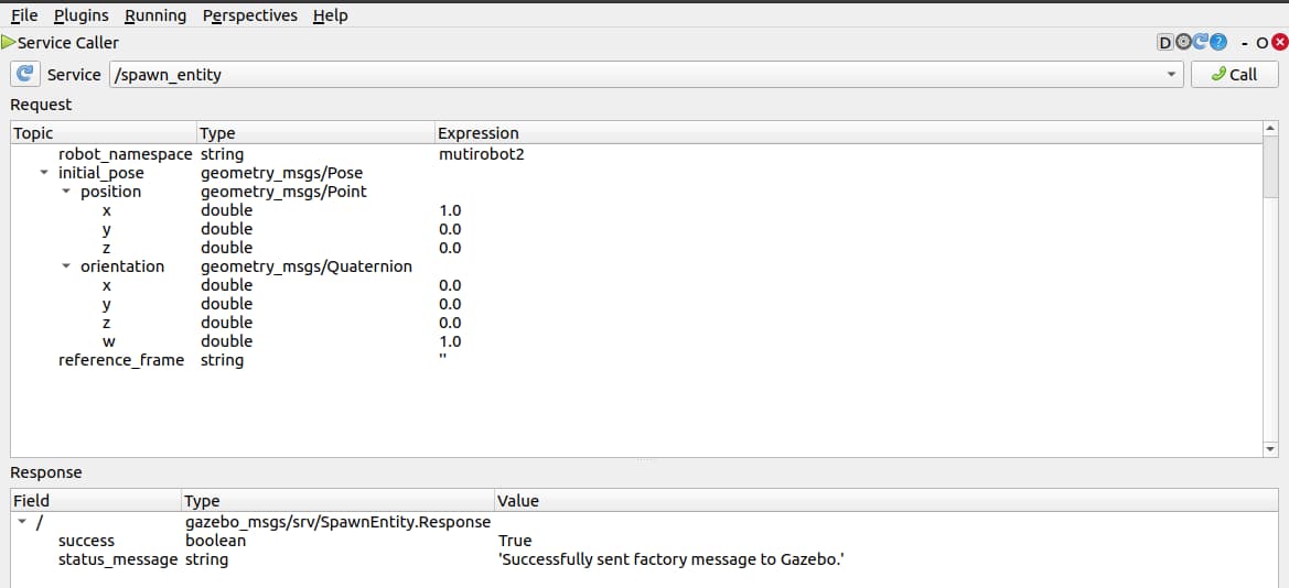
- string robot_namespace ,产生的机器人和所有的ROS接口的命名空间,多机器人仿真的时候很有用。
- geometry_msgs/Pose initial_pose ,机器人的初始化位置
- string reference_frame ,初始姿态是相对于该实体的frame定义的。如果保持"empty"或"world"或"map",则使用 gazebo的world作为frame。如果指定了不存在的实体,则会返回错误
调用服务加载fishbot
在rqt工具集里有一个叫服务请求工具。
命令行输入rqt,在插件选项中选择Services->Service Caller,然后再下拉框选择/spawn_entity服务。
接着我们把我们的FishBot的URDF模型复制粘贴,放到xml中(注意要把原来的''删掉哦!)
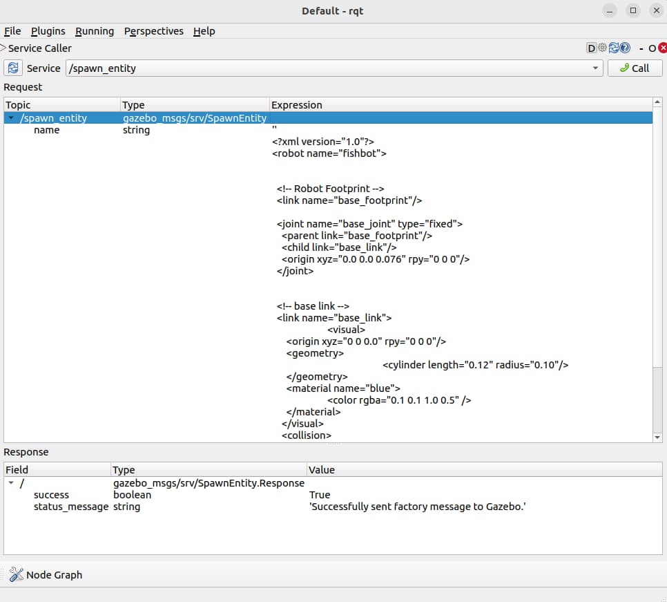
接着就可以看到工厂返回说成功把机器人制作出来送入gazebo了。
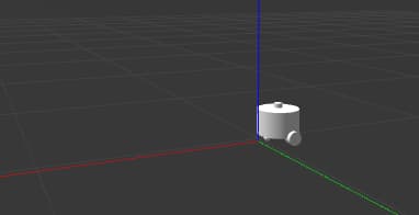
此时再看我们的Gazebo,一个小小的,白白的机器人出现了。
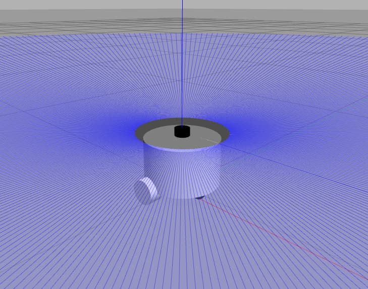
按住Shift加鼠标左键,拖动一下,来好好的欣赏欣赏我们的机器人。
在不同位置加载多个机器人
欣赏完毕后,小鱼再带你生产一个fishbot(为了后面需要多机器人仿真的小伙伴)。
修改rqt中的参数,增加一个命名空间,然后修改一个位置,让第二个机器人和第一个相距1m的地方生产,然后点击Call。
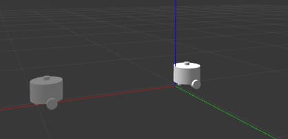
返回成功,此时拖送Gazebo观察一下,发现多出了一个机器人,距离刚好是在X轴(红色)1米(一个小格子一米)处。
查询和删除机器人
利用rqt工具,我们再对另外两个服务接口进行请求。
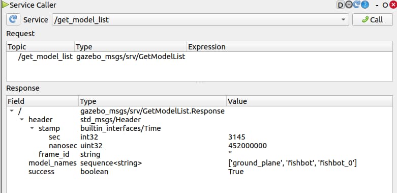
查到了三个模型,一个大地,一个fishbot,一个fishbot_0。
我们接着尝试把fishbot_0删掉,选择删除实体,输入fishbot_0的名字,拿起小电话通知工厂回收我们的0号fishbot。
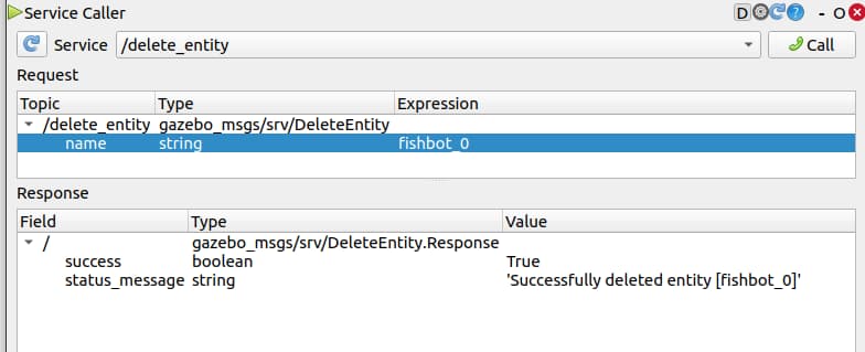
调用成功,观察gazebo发现机器人没了
将启动gazebo和生产fishbot写成launch文件
打开fishbot工作空间,在src/fishbot_description/launch中添加一个gazebo.launch.py文件,我们开始编写launch文件来在gazebo中加载机器人模型。
启动gazebo,我们可以将命令行写成一个launch节点
ExecuteProcess(
        cmd=['gazebo', '--verbose','-s', 'libgazebo_ros_init.so', '-s', 'libgazebo_ros_factory.so', gazebo_world_path],
        output='screen')
上面我们加载机器人是直接将XML格式的URDF复制过去进行加载的,这样很不方便,我们可以使用gazebo_ros为我们提供好的一个叫做spawn_entity.py节点,该节点支持从文件地址直接生产机器人到Gazebo。
其实该节点的原理也很简单,从URDF中读取机器人模型,然后再调用服务,和我们手动操作一个样。
该节点需要两个参数,一个机器人的模型名字和urdf的文件地址,这个简单,前面我们曾经使用package_share来拼接过urdf路径。
spawn_entity_cmd = Node(
    package='gazebo_ros',
    executable='spawn_entity.py',
    arguments=['-entity', robot_name_in_model,  '-file', urdf_model_path ], output='screen')
最终写好的launch文件如下:
import os
from launch import LaunchDescription
from launch.actions import ExecuteProcess
from launch_ros.actions import Node
from launch_ros.substitutions import FindPackageShare


def generate_launch_description():
    robot_name_in_model = 'fishbot'
    package_name = 'fishbot_description'
    urdf_name = "fishbot_gazebo.urdf"

    ld = LaunchDescription()
    pkg_share = FindPackageShare(package=package_name).find(package_name)
    urdf_model_path = os.path.join(pkg_share, f'urdf/{urdf_name}')

    # Start Gazebo server
    start_gazebo_cmd =  ExecuteProcess(
        cmd=['gazebo', '--verbose','-s', 'libgazebo_ros_init.so', '-s', 'libgazebo_ros_factory.so'],
        output='screen')

    # Launch the robot
    spawn_entity_cmd = Node(
        package='gazebo_ros',
        executable='spawn_entity.py',
        arguments=['-entity', robot_name_in_model,  '-file', urdf_model_path ], output='screen')

    ld.add_action(start_gazebo_cmd)
    ld.add_action(spawn_entity_cmd)


    return ld
编译运行
colcon build --packages-select fishbot_description
source install/setup.bash
ros2 launch fishbot_description gazebo.launch.py
完美显示
Gazebo仿真插件之两轮差速
Gazebo插件介绍
gazebo的插件按照用途大致可以分为两种:
- 用于控制的插件,通过插件可以控制机器人关节运动,可以进行位置、速度、力的控制,比如我们这节课的两轮差速控制器。
- 用于数据采集的插件,比如IMU传感器用于采集机器人的惯性,激光雷达用于采集机器人周围的点云信息。
当然上面两类插件功能也可以写到一个插件里,两轮差速插件就是一个二合一加强版。
两轮差速插件介绍
两轮差速插件用于控制机器人轮子关节的位置变化,同时该插件还会获取轮子的位置以及速度的信息的反馈,根据反馈的位置信息结合运动学模型即可计算出当前机器人的位姿(里程计)。
该插件的名称为:gazebo_ros_diff_drive
两轮差速控制器和Gazebo的关系
两轮差速控制器可以将轮子的目标转速发送给Gazebo,并从Gazebo获取到实际的速度和位置。
注意:发送给Gazebo是目标速度,反馈回来的是实际速度。目标!=实际,比如轮子卡住了,无论你发什么目标速度,实际速度都是0。
要想快速了解一个系统的功能,最直接的就是看系统的对外的输入和输出是什么?什么都不要说,看下图:
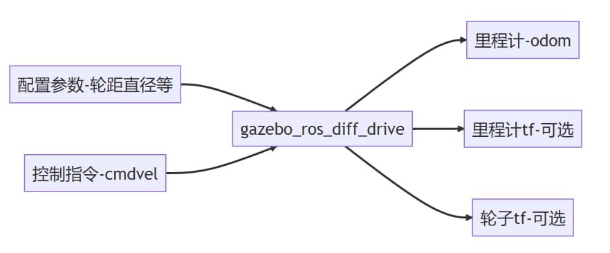
上图就是对gazebo_ros_diff_drive的输入和输出信息的总结,可以很直观的看到该插件主要输入控制指令,主要输出里程计信息。
输入参数
配置参数
| 配置项 | 含义 |
|---|---|
| ros | ros相关配置,包含命名空间和话题重映射等 |
| update_rate | 数据更新速率 |
| left_joint | 左轮关节名称 |
| right_joint | 右轮关节名称 |
| wheel_separation | 左右轮子的间距 |
| wheel_diameter | 轮子的直径 |
| max_wheel_torque | 轮子最大的力矩 |
| max_wheel_acceleration | 轮子最大的加速度 |
| publish_odom | 是否发布里程计 |
| publish_odom_tf | 是否发布里程计的tf开关 |
| publish_wheel_tf | 是否发布轮子的tf数据开关 |
| odometry_frame | 里程计的framed ID,最终体现在话题和TF上 |
| robot_base_frame | 机器人的基础frame的ID |
控制指令
两轮差速控制器默认通过订阅话题cmd_vel来获取目标线速度和角速度。该话题的类型为:geometry_msgs/msg/Twist
我们通过ros2的CLI来看一下这个消息包含的内容有哪些?
ros2 interface show geometry_msgs/msg/Twist
# This expresses velocity in free space broken into its linear and angular parts.

Vector3  linear
Vector3  angular
可以看到包含线速度和角速度,我们用proto在看一下包含的基本数据类型有哪些?
ros2 interface proto geometry_msgs/msg/Twist
"linear:
  x: 0.0
  y: 0.0
  z: 0.0
angular:
  x: 0.0
  y: 0.0
  z: 0.0
"
线速度和角速度都包含在x、y、z,代表坐标系的三个方向上的对应速度。
两轮差速控制器收到这个话题数据后将其中的角速度和线速度转换上两个轮子的转动速度发送给Gazebo。
输出参数
里程计
里程计信息默认的输出话题为odom,其消息类型为:nav_msgs/msg/Odometry
同样的使用CLI看一下其消息的组成结构:
ros2 interface show nav_msgs/msg/Odometry
# This represents an estimate of a position and velocity in free space.
# The pose in this message should be specified in the coordinate frame given by header.frame_id
# The twist in this message should be specified in the coordinate frame given by the child_frame_id

# Includes the frame id of the pose parent.
std_msgs/Header header

# Frame id the pose points to. The twist is in this coordinate frame.
string child_frame_id

# Estimated pose that is typically relative to a fixed world frame.
geometry_msgs/PoseWithCovariance pose

# Estimated linear and angular velocity relative to child_frame_id.
geometry_msgs/TwistWithCovariance twist
ros2 interface proto nav_msgs/msg/Odometry
"header:
  stamp:
    sec: 0
    nanosec: 0
  frame_id: ''
child_frame_id: ''
pose:
  pose:
    position:
      x: 0.0
      y: 0.0
      z: 0.0
    orientation:
      x: 0.0
      y: 0.0
      z: 0.0
      w: 1.0
  covariance:
  - 0.0
  - 0.0
    ...
twist:
  twist:
    linear:
      x: 0.0
      y: 0.0
      z: 0.0
    angular:
      x: 0.0
      y: 0.0
      z: 0.0
  covariance:
  - 0.0
  - 0.0
    ...
"
可以看到其数据主要包含三个部分:
- header,表示该消息发布的时间
- pose,表示当前机器人位置和朝向
- twist,表示当前机器人的线速度和角速度
数据中还包含一个covariance,其代表协方差矩阵,后面小鱼写篇文章来介绍下,这里只需了解其含义即可。
里程计TF信息
设为true,订阅tf话题里你就可以看到像下面的msg,建议后面配置好后,手动修改下,对比区别
- header:
    stamp:
      sec: 6157
      nanosec: 907000000
    frame_id: odom
  child_frame_id: base_footprint
  transform:
    translation:
      x: 0.0005557960241049835
      y: -0.0007350446303238693
      z: 0.01599968753145574
    rotation:
      x: 4.691143395208505e-07
      y: 7.115496626557812e-06
      z: -0.018531475772549166
      w: 0.9998282774331005
左右轮子TF信息
设为true,订阅tf话题里你就可以看到像下面的msg,建议后面配置好后,手动修改下,对比区别
- header:
    stamp:
      sec: 6157
      nanosec: 941000000
    frame_id: base_link
  child_frame_id: left_wheel_link
  transform:
    translation:
      x: -0.02
      y: 0.1
      z: -0.06
    rotation:
      x: 0.0
      y: 0.049519025127821005
      z: 0.0
      w: 0.9987731805321918
- header:
    stamp:
      sec: 6157
      nanosec: 941000000
    frame_id: base_link
  child_frame_id: right_wheel_link
  transform:
    translation:
      x: -0.02
      y: -0.1
      z: -0.06
    rotation:
      x: 0.0
      y: -0.0663387077034509
      z: 0.0
      w: 0.9977971616817898
在URDF中配置两轮差速模型
上面该介绍的我们都给介绍了,接着我们直接来配置。
因为是给Gazebo的插件,所以在URDF中,我们需要使用**进行配置,因为是要给gazebo配置插件,所有要在gazebo标签下添加plugin**子插件。
  <gazebo>
    <plugin name='diff_drive' filename='libgazebo_ros_diff_drive.so'>
          <ros>
            <namespace>/</namespace>
            <remapping>cmd_vel:=cmd_vel</remapping>
            <remapping>odom:=odom</remapping>
          </ros>
          <update_rate>30</update_rate>
          <!-- wheels -->
          <left_joint>left_wheel_joint</left_joint>
          <right_joint>right_wheel_joint</right_joint>
          <!-- kinematics -->
          <wheel_separation>0.2</wheel_separation>
          <wheel_diameter>0.065</wheel_diameter>
          <!-- limits -->
          <max_wheel_torque>20</max_wheel_torque>
          <max_wheel_acceleration>1.0</max_wheel_acceleration>
          <!-- output -->
          <publish_odom>true</publish_odom>
          <publish_odom_tf>true</publish_odom_tf>
          <publish_wheel_tf>true</publish_wheel_tf>
          <odometry_frame>odom</odometry_frame>
          <robot_base_frame>base_footprint</robot_base_frame>
      </plugin>
将这段代码加到我们的URDF中,然后对着上面小鱼介绍的配置项,一一看下,接着我们就可以来测试运行了。
两轮差速插件测试
修改完了URDF模型我们将代码编译一下,让更新后的URDF文件安装到install目录,接着就可以运行9.2中的launch文件,将模型加载到Gazebo中。
编译-启动
colcon build
source install/setup.bash
ros2 launch fishbot_description gazebo.launch.py
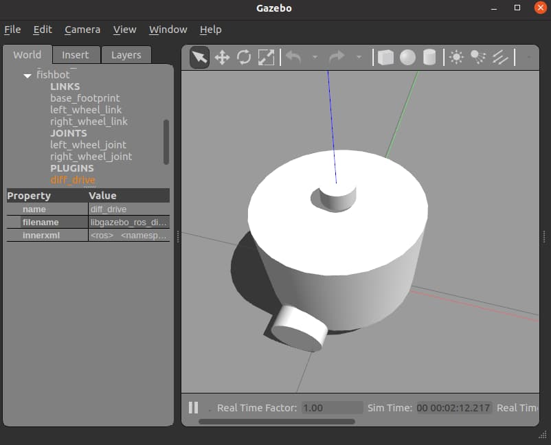
接着你可以使用CLI工具看一下系统有哪些节点在运行
ros2 node list
ros2 topic list
ros2 node list
---------------
/diff_drive
/gazebo

ros2 topic list
---------------
/clock
/cmd_vel
/odom
/parameter_events
/performance_metrics
/rosout
/tf
相信此时你已经看到了我们插件订阅的的/cmd_vel和发布的/odom了。
使用键盘控制fishbot
你还记得第二章中小鱼带你玩的小乌龟吗?当时我们用键盘来控制小乌龟运动,现在我们可以用键盘来控制fishbot动起来了。
你需要一个键盘控制工具,可以用下面的指令安装
sudo apt install ros-humble-teleop-twist-keyboard
这个功能包下有一个节点,这个节点会监听键盘的按键事件,然后发布cmd_vel话题,该话题被gazebo的两轮差速插件所订阅。所以我们就可以通过这个节点来控制fishbot。
ros2 run teleop_twist_keyboard teleop_twist_keyboard
如果你想让这个节点不是发布cmd_vel话题,而是别的,可以采用ROS2的话题重映射功能。 eg: ros2 run teleop_twist_keyboard teleop_twist_keyboard --ros-args --remap cmd_vel:=cmd_vel1
接着尝试使用来控制机器人运动
   U    I    O
   J    K    L
   M    <    >
点一下I,你就能看到fishbot在Gazebo中飞速的移动。接着打开终端,打印一下odom话题和tf话题,移动机器人观察数据变化。
此时你应该玩一会,体验一下各种花式走法。
使用rqt显示速度数据
接着我们尝试使用rqt将数据在rqt中可视化出来,打开终端输入rqt。
rqt
选择Plugin->Visualization->Plot
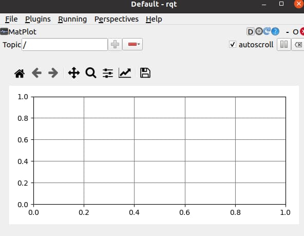
在上方Topic输入/cmd_vel/linear/x,再输入/cmd_vel/angular/z,然后用键盘控制机器人移动。
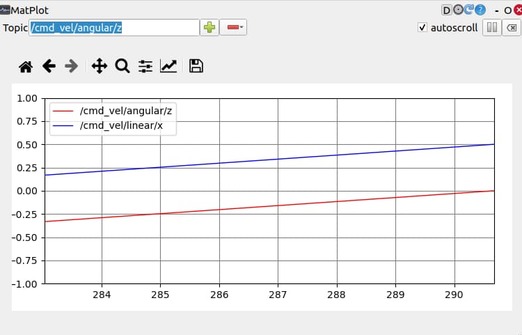
cmd_vel中的速度代表目标速度,接着我们显示一下当前速度(在odom.twist中)
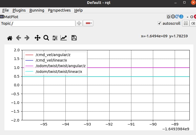
在RVIZ2中显示Fishbot及其轨迹
打开rviz2
rviz2
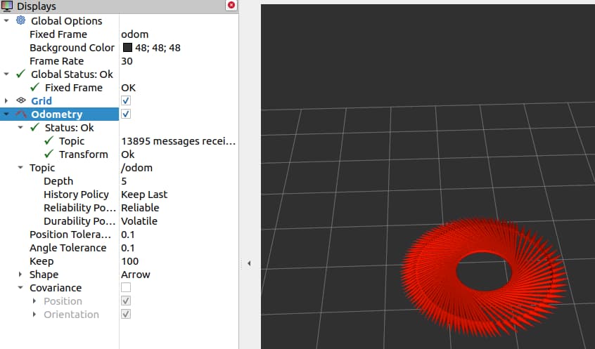
- 修改FixedFrame为odom
- 添加插件,Add->Odometry->OK
- 选择话题,Odometry->Topic->选/odom
- 去除协方差显示,Odometry->Covariance>取消勾选
- 键盘控制节点,点个U,原地转圈圈
最终结果:
在RVIZ2中显示机器人模型
虽然机器人的轨迹已经在RVIZ中显示出来了,但是并没有机器人的模型,也看不到轮子的转动
要发布机器人模型我们所使用的节点是robot_state_publisher,所以我们在gazebo.launch.py中加入这个节点,同时再加上rviz2的启动节点,最终的gazebo.launch.py内容如下:
import os
from launch import LaunchDescription
from launch.actions import ExecuteProcess
from launch_ros.actions import Node
from launch_ros.substitutions import FindPackageShare


def generate_launch_description():
    robot_name_in_model = 'fishbot'
    package_name = 'fishbot_description'
    urdf_name = "fishbot_gazebo.urdf"

    ld = LaunchDescription()
    pkg_share = FindPackageShare(package=package_name).find(package_name)
    urdf_model_path = os.path.join(pkg_share, f'urdf/{urdf_name}')

    # Start Gazebo server
    start_gazebo_cmd =  ExecuteProcess(
        cmd=['gazebo', '--verbose','-s', 'libgazebo_ros_init.so', '-s', 'libgazebo_ros_factory.so', gazebo_world_path],
        output='screen')

    # Launch the robot
    spawn_entity_cmd = Node(
        package='gazebo_ros',
        executable='spawn_entity.py',
        arguments=['-entity', robot_name_in_model,  '-file', urdf_model_path ], output='screen')

    # Start Robot State publisher
    start_robot_state_publisher_cmd = Node(
        package='robot_state_publisher',
        executable='robot_state_publisher',
        arguments=[urdf_model_path]
    )

    # Launch RViz
    start_rviz_cmd = Node(
        package='rviz2',
        executable='rviz2',
        name='rviz2',
        output='screen',
        # arguments=['-d', default_rviz_config_path]
        )

    ld.add_action(start_gazebo_cmd)
    ld.add_action(spawn_entity_cmd)
    ld.add_action(start_robot_state_publisher_cmd)
    ld.add_action(start_rviz_cmd)


    return ld
保存编译启动
colcon build
ros2 launch fishbot_description gazebo.launch.py
然后继续启动键盘控制,Enjoy It!
Gazebo仿真插件之IMU
惯性测量单元IMU介绍
惯性测量单元是测量物体三轴姿态角(或角速率)以及加速度的装置。一般的,一个IMU包含了三个单轴的加速度计和三个单轴的陀螺,加速度计检测物体在载体坐标系统独立三轴的加速度信号,而陀螺检测载体相对于导航坐标系的角速度信号,测量物体在三维空间中的角速度和加速度,并以此解算出物体的姿态。在导航中有着很重要的应用价值。
上面这段话是从百科中摘抄出来的,你需要知道的一个关键点是IMU可以测量以下三组数据:
- 三维角度
- 三维加速度
- 三维角速度
Gazebo-IMU插件介绍
仿真的IMU也是对应一个后缀为.so的动态链接库,使用下面的指令可以查看所有的动态链接库:
ls /opt/ros/humble/lib/libgazebo_ros*
/opt/ros/humble/lib/libgazebo_ros2_control.so
/opt/ros/humble/lib/libgazebo_ros_ackermann_drive.so
/opt/ros/humble/lib/libgazebo_ros_bumper.so
/opt/ros/humble/lib/libgazebo_ros_camera.so
/opt/ros/humble/lib/libgazebo_ros_diff_drive.so
/opt/ros/humble/lib/libgazebo_ros_elevator.so
/opt/ros/humble/lib/libgazebo_ros_factory.so
/opt/ros/humble/lib/libgazebo_ros_force.so
/opt/ros/humble/lib/libgazebo_ros_force_system.so
/opt/ros/humble/lib/libgazebo_ros_ft_sensor.so
/opt/ros/humble/lib/libgazebo_ros_gps_sensor.so
/opt/ros/humble/lib/libgazebo_ros_hand_of_god.so
/opt/ros/humble/lib/libgazebo_ros_harness.so
/opt/ros/humble/lib/libgazebo_ros_imu_sensor.so
/opt/ros/humble/lib/libgazebo_ros_init.so
/opt/ros/humble/lib/libgazebo_ros_joint_pose_trajectory.so
/opt/ros/humble/lib/libgazebo_ros_joint_state_publisher.so
/opt/ros/humble/lib/libgazebo_ros_node.so
/opt/ros/humble/lib/libgazebo_ros_p3d.so
/opt/ros/humble/lib/libgazebo_ros_planar_move.so
/opt/ros/humble/lib/libgazebo_ros_projector.so
/opt/ros/humble/lib/libgazebo_ros_properties.so
/opt/ros/humble/lib/libgazebo_ros_ray_sensor.so
/opt/ros/humble/lib/libgazebo_ros_state.so
/opt/ros/humble/lib/libgazebo_ros_template.so
/opt/ros/humble/lib/libgazebo_ros_tricycle_drive.so
/opt/ros/humble/lib/libgazebo_ros_utils.so
/opt/ros/humble/lib/libgazebo_ros_vacuum_gripper.so
/opt/ros/humble/lib/libgazebo_ros_video.so
/opt/ros/humble/lib/libgazebo_ros_wheel_slip.so
IMU对应的消息类型为sensor_msgs/msg/Imu
ros2 interface show sensor_msgs/msg/Imu
# This is a message to hold data from an IMU (Inertial Measurement Unit)
#
# Accelerations should be in m/s^2 (not in g's), and rotational velocity should be in rad/sec
#
# If the covariance of the measurement is known, it should be filled in (if all you know is the
# variance of each measurement, e.g. from the datasheet, just put those along the diagonal)
# A covariance matrix of all zeros will be interpreted as "covariance unknown", and to use the
# data a covariance will have to be assumed or gotten from some other source
#
# If you have no estimate for one of the data elements (e.g. your IMU doesn't produce an
# orientation estimate), please set element 0 of the associated covariance matrix to -1
# If you are interpreting this message, please check for a value of -1 in the first element of each
# covariance matrix, and disregard the associated estimate.

std_msgs/Header header

geometry_msgs/Quaternion orientation
float64[9] orientation_covariance # Row major about x, y, z axes

geometry_msgs/Vector3 angular_velocity
float64[9] angular_velocity_covariance # Row major about x, y, z axes

geometry_msgs/Vector3 linear_acceleration
float64[9] linear_acceleration_covariance # Row major x, y z
可以看到除了每个数据对应的三个协方差之外,每一个还都对应一个3*3的协方差矩阵。
给FIshbot配置IMU传感器
高斯噪声只需要指定平均值和标准差两个参数即可,不过因为IMU传感器的特殊性,我们还需要给模型添加两个偏差参数,分别是 平均值偏差 和 标准差偏差 。
下面是IMU传感器的URDF配置代码,大家结合文章对应可以理解一下,IMU对应的插件库libgazebo_ros_imu_sensor.so
    <gazebo reference="imu_link">
      <sensor name="imu_sensor" type="imu">
      <plugin filename="libgazebo_ros_imu_sensor.so" name="imu_plugin">
          <ros>
            <namespace>/</namespace>
            <remapping>~/out:=imu</remapping>
          </ros>
          <initial_orientation_as_reference>false</initial_orientation_as_reference>
        </plugin>
        <always_on>true</always_on>
        <update_rate>100</update_rate>
        <visualize>true</visualize>
        <imu>
          <angular_velocity>
            <x>
              <noise type="gaussian">
                <mean>0.0</mean>
                <stddev>2e-4</stddev>
                <bias_mean>0.0000075</bias_mean>
                <bias_stddev>0.0000008</bias_stddev>
              </noise>
            </x>
            <y>
              <noise type="gaussian">
                <mean>0.0</mean>
                <stddev>2e-4</stddev>
                <bias_mean>0.0000075</bias_mean>
                <bias_stddev>0.0000008</bias_stddev>
              </noise>
            </y>
            <z>
              <noise type="gaussian">
                <mean>0.0</mean>
                <stddev>2e-4</stddev>
                <bias_mean>0.0000075</bias_mean>
                <bias_stddev>0.0000008</bias_stddev>
              </noise>
            </z>
          </angular_velocity>
          <linear_acceleration>
            <x>
              <noise type="gaussian">
                <mean>0.0</mean>
                <stddev>1.7e-2</stddev>
                <bias_mean>0.1</bias_mean>
                <bias_stddev>0.001</bias_stddev>
              </noise>
            </x>
            <y>
              <noise type="gaussian">
                <mean>0.0</mean>
                <stddev>1.7e-2</stddev>
                <bias_mean>0.1</bias_mean>
                <bias_stddev>0.001</bias_stddev>
              </noise>
            </y>
            <z>
              <noise type="gaussian">
                <mean>0.0</mean>
                <stddev>1.7e-2</stddev>
                <bias_mean>0.1</bias_mean>
                <bias_stddev>0.001</bias_stddev>
              </noise>
            </z>
          </linear_acceleration>
        </imu>
      </sensor>
    </gazebo>
将上面的代码加到fishbot_gazebo.urdf中,接着我们就可以进行测试了。
编译测试
编译
colcon build
运行
ros2 launch fishbot_description gazebo.launch.py
CLI看话题
ros2 topic list
ros2 topic info /imu
ros2 topic echo /imu
输出:
header:
  stamp:
    sec: 150
    nanosec: 599000000
  frame_id: base_footprint
orientation:
  x: 3.434713830866392e-07
  y: 7.119913105768616e-06
  z: -0.00028312437320413914
  w: 0.9999999598948884
orientation_covariance:
- 0.0
- 0.0
- 0.0
- 0.0
- 0.0
- 0.0
- 0.0
- 0.0
- 0.0
angular_velocity:
  x: -0.00013597855247901325
  y: 0.0006306135617081868
  z: -0.00015794894627685146
angular_velocity_covariance:
- 4.0e-08
- 0.0
- 0.0
- 0.0
- 4.0e-08
- 0.0
- 0.0
- 0.0
- 4.0e-08
linear_acceleration:
  x: 0.08679200038530369
  y: 0.07753419258567491
  z: 9.687910969061628
linear_acceleration_covariance:
- 0.00028900000000000003
- 0.0
- 0.0
- 0.0
- 0.00028900000000000003
- 0.0
- 0.0
- 0.0
- 0.00028900000000000003
用rqt可视化:
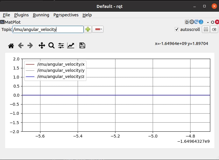
为FishBot添加添加激光雷达传感器
传感器在自动驾驶、室内导航等应用非常多,比如扫地机器人上就是用的它作为感知环境的重要工具,该传感器是激光雷达。
激光雷达介绍
激光雷达(Light Detection And Ranging),缩写LiDAR,翻译一下叫——激光探测与测距。
激光雷达原理介绍
激光雷达的原理也很简单,就像蝙蝠的定位方法一样,蝙蝠定位大家都知道吧,像下面这样子的回声定位。
普通的单线激光雷达一般有一个发射器,一个接收器,发射器发出激光射线到前方的目标上,物品会将激光反射回来,然后激光雷达的接受器可以检测到反射的激光。
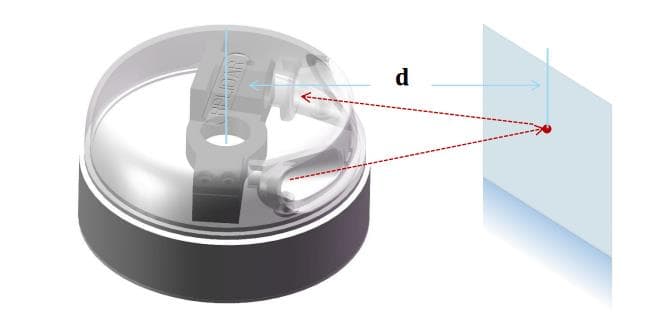
通过计算发送和反馈之间的时间间隔,乘上激光的速度,就可以计算出激光飞行的距离,该计算方法成为TOF(飞行时间法Time of flight,也称时差法)。
除了TOF之外还有其他方法进行测距,比如三角法,这里就不拓展了放一篇文章,大家自行阅读。
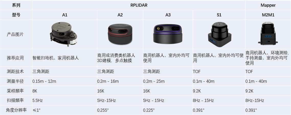
需要注意的是虽然只有一个发射器和一个接受器,激光雷达通过电机可以进行旋转,这样就可以达到对周围环境360度测距的目的。
激光雷达大赏
Gazebo激光雷达插件
因为激光雷达是属于射线类传感器,该类传感在在Gazebo插件中都被封装成了一个动态库libgazebo_ros_ray_sensor.so,接着我们来看看LiDAR的话题消息接口sensor_msgs/msg/LaserScan。
ros2 interface show sensor_msgs/msg/LaserScan
# Single scan from a planar laser range-finder
#
# If you have another ranging device with different behavior (e.g. a sonar
# array), please find or create a different message, since applications
# will make fairly laser-specific assumptions about this data

std_msgs/Header header # timestamp in the header is the acquisition time of
                             # the first ray in the scan.
                             #
                             # in frame frame_id, angles are measured around
                             # the positive Z axis (counterclockwise, if Z is up)
                             # with zero angle being forward along the x axis

float32 angle_min            # start angle of the scan [rad]
float32 angle_max            # end angle of the scan [rad]
float32 angle_increment      # angular distance between measurements [rad]

float32 time_increment       # time between measurements [seconds] - if your scanner
                             # is moving, this will be used in interpolating position
                             # of 3d points
float32 scan_time            # time between scans [seconds]

float32 range_min            # minimum range value [m]
float32 range_max            # maximum range value [m]

float32[] ranges             # range data [m]
                             # (Note: values < range_min or > range_max should be discarded)
float32[] intensities        # intensity data [device-specific units].  If your
                             # device does not provide intensities, please leave
                             # the array empty.
为FishBot添加雷达插件
有了前面的经验,我们需要在URDF添加以下内容即可
  <gazebo reference="laser_link">
      <sensor name="laser_sensor" type="ray">
      <always_on>true</always_on>
      <visualize>true</visualize>
      <update_rate>5</update_rate>
      <pose>0 0 0.075 0 0 0</pose>
      <ray>
          <scan>
            <horizontal>
              <samples>360</samples>
              <resolution>1.000000</resolution>
              <min_angle>0.000000</min_angle>
              <max_angle>6.280000</max_angle>
            </horizontal>
          </scan>
          <range>
            <min>0.120000</min>
            <max>3.5</max>
            <resolution>0.015000</resolution>
          </range>
          <noise>
            <type>gaussian</type>
            <mean>0.0</mean>
            <stddev>0.01</stddev>
          </noise>
      </ray>

      <plugin name="laserscan" filename="libgazebo_ros_ray_sensor.so">
        <ros>
          <remapping>~/out:=scan</remapping>
        </ros>
        <output_type>sensor_msgs/LaserScan</output_type>
        <frame_name>laser_link</frame_name>
      </plugin>
      </sensor>
    </gazebo>
可以看到:
- 雷达也可以设置更新频率update_rate,这里设置为5
- 雷达可以设置分辨率,设置为1,采样数量360个,最终生成的点云数量就是360
- 雷达也有噪声,模型为gaussian
- 雷达有扫描范围range,这里配置成0.12-3.5,0.015分辨率
- 雷达的pose就是雷达的joint中位置的设置值
编译测试
编译
colcon build
source install/setup.bash
运行
ros2 launch fishbot_description gazebo.launch.py
CLI看话题
ros2 topic list
ros2 topic info /scan
ros2 topic echo /scan
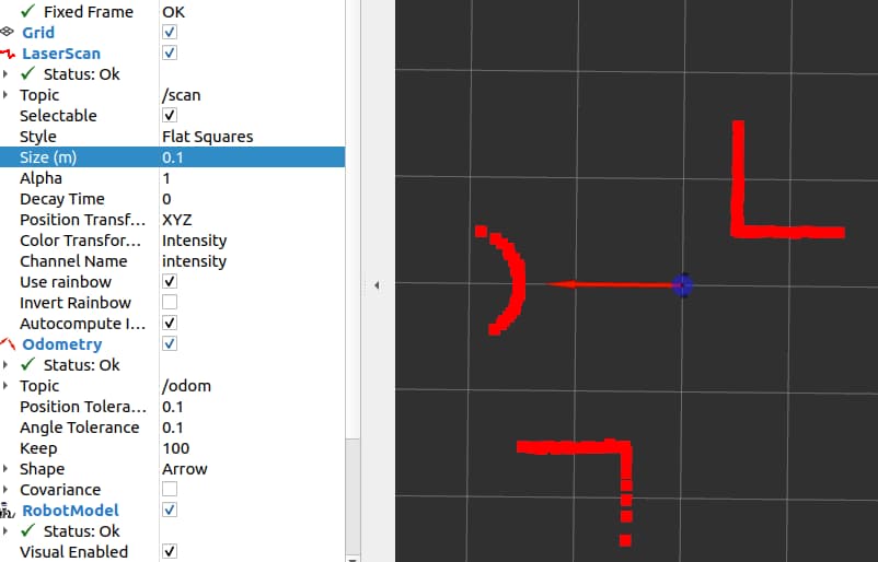
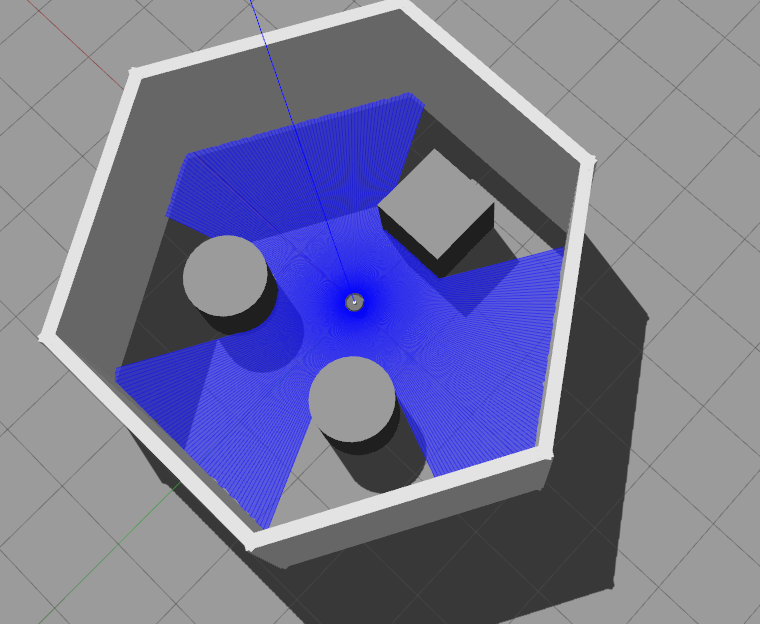
接着我们尝试使用rviz2进行可视化激光雷达数据
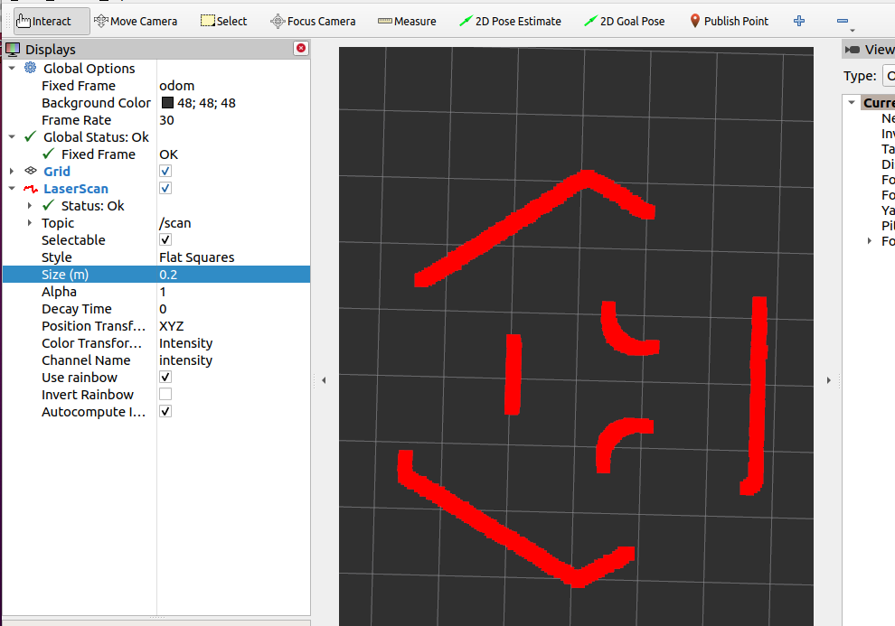
添加和修改RVIZ2的如下:(通过LaserScan插件可以看到激光数据)
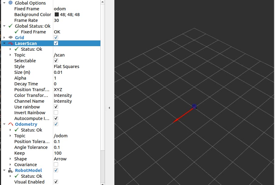
相信你改完之后依然是看不到任何激光雷达的数据的,反看topic的echo出来的数据,不是0就是inf(无限大),再看看gazebo你会发现,激光雷达并没有达到任何一个物体上。
所以我们可以手动的给激光雷达周围添加一下东西,点击Gazebo工具栏的正方体,圆球或者圆柱,随意放置几个到我们激光雷达的最大扫描半径内。
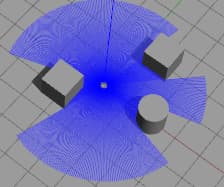
接着我们再看一下RVIZ2,这里小鱼把size改大了10倍0.01->0.1。
Gazebo仿真环境搭建
Gazebo的world介绍
world即世界,gazebo的world文件就是用于描述世界模型的,也就是环境模型。
但是一开始安装Gazebo的时候并不会帮你下载好这些模型,需要我们手动下载,万幸的是小鱼已经帮你封装成了一行代码下载指令,打开终端,复制粘贴下面这句
cd ~/.gazebo && wget https://gitee.com/ohhuo/scripts/raw/master/gazebo_model.py && python3 gazebo_model.py
然后等待脚本运行完成,当然也不用等它完成,因为一共有281个模型,是逐一下载并解压到 ~/.gazebo/models/ 目录的。
此时再次打开终端,输入gazebo,把选项卡切换到Insert
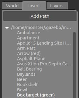
在Insert选项卡下可以看到一个目录,以及目录下的模型名称,随着下载脚本的不断下载,这里的模型会越来越多。
通过建墙工具建立world
Gazebo左上角->Edit->Building Editor
接着可以看到这样一个编辑界面
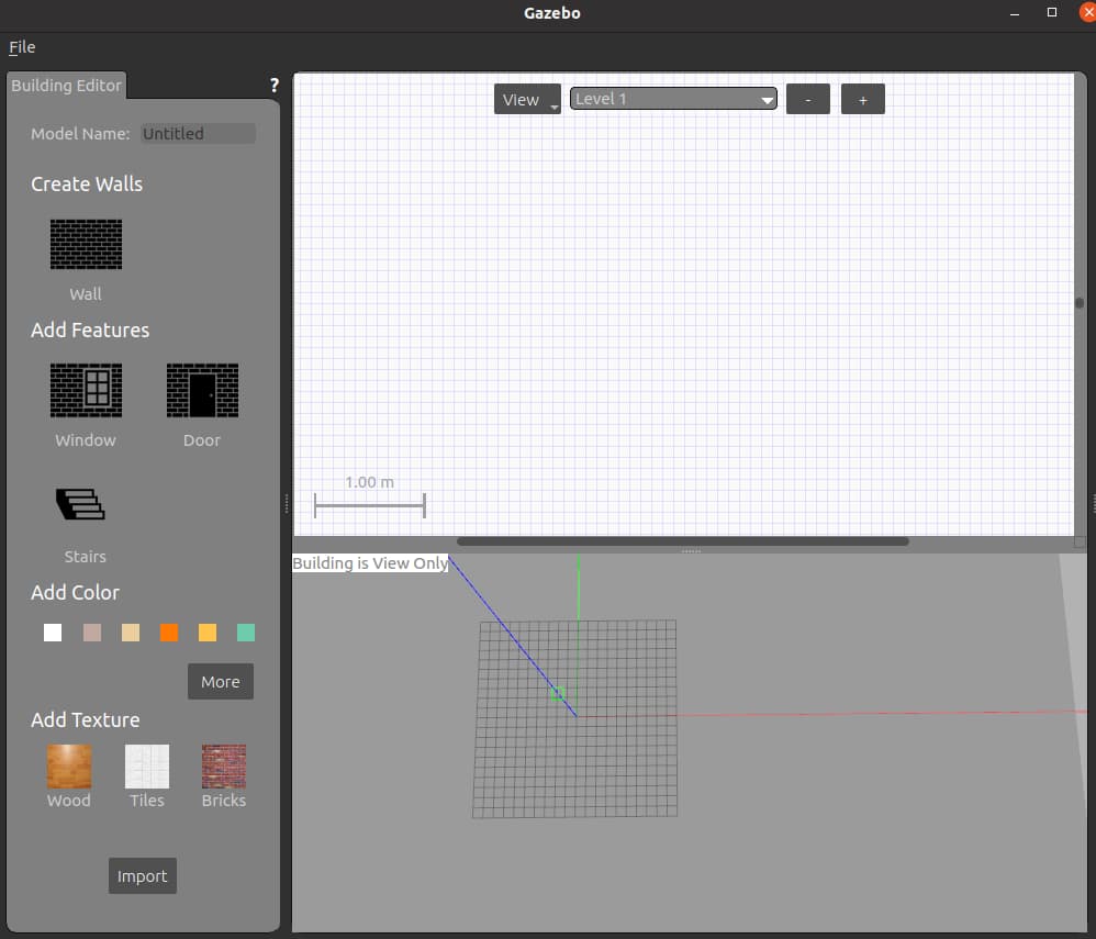
随手画墙
点击左边的Wall,你就可以在上方的白色区域进行建墙了。
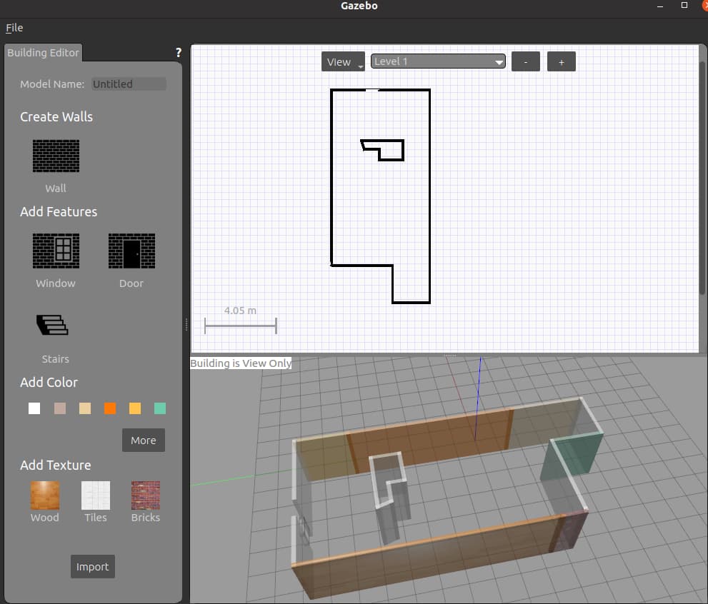
建完后还可以用选Add Color或者Add Texture,然后点击下方墙,给墙添加颜色或者纹理。
从已有地图画墙
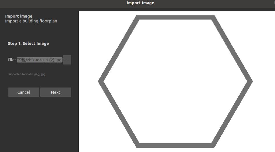
首先你要有一个地图,小鱼为你准备了两个,两个图片都是800*600像素的。

打开Gazebo->Gazebo左上角->Edit->Building Editor->左下方选Import

将上面两个图片存到本地,在这个界面选图片,记着选Next
左边选尺寸对应关系
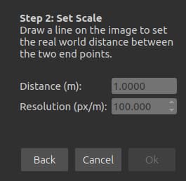
我们选择默认的,100像素/米。点击OK(需要手动将100改变一下才能点击OK哦),之后就可以用图片画墙了。
注意:导入完图片不会直接出来墙,图片只是提供了墙的大概位置,需要你手动用墙再将边描一遍。
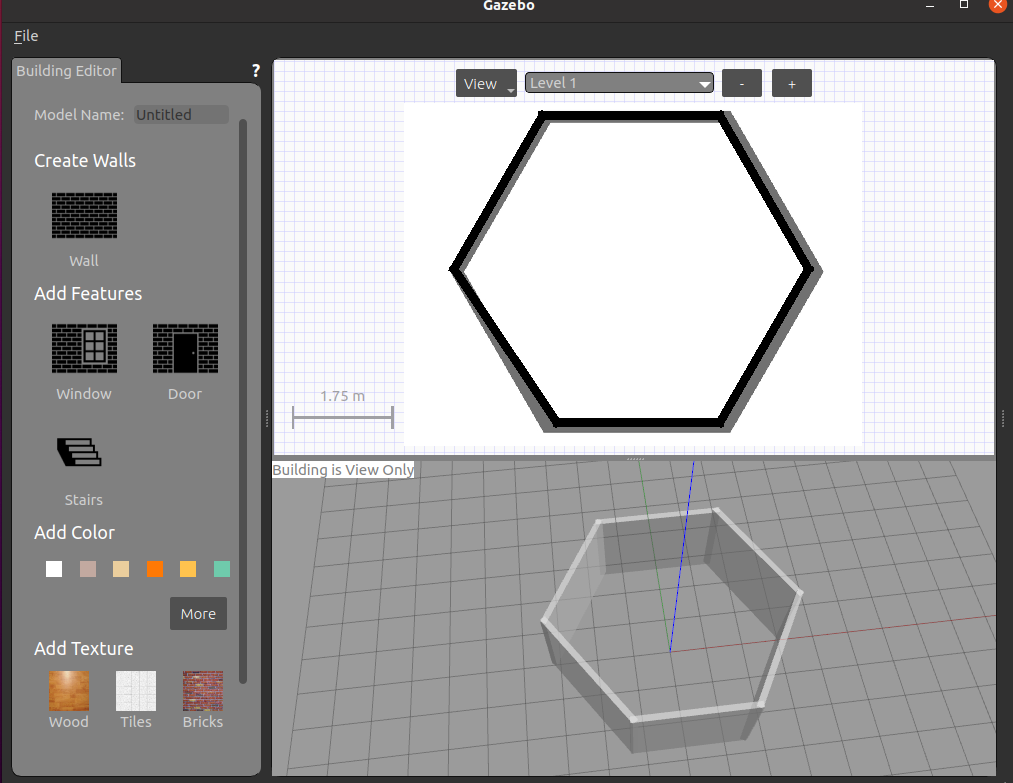
建完后点击File->Exit,在退出的弹框中选Exit。
接着在Gazebo界面中就可以看到墙了,我们再手动添加几个物体,就可以用于下面的导航使用了。
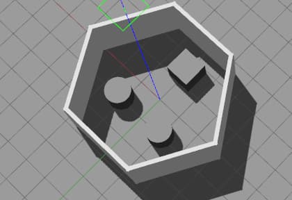
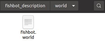
添加完,接着点击File->SaveWorld,将文件保存到我们的fishbot_descrption的world下。
没有world目录的小伙伴可以先手动创建下

点击右上角Sace,在文件夹就可以看到这个world文件
启动时加载world
命令行加载World
加载world其实也很简单,可以先启动Gazebo,再手动的加载文件,也可以在Gazebo启动时加载:
比如在前面加载ROS2插件基础上再加载fishbot.world。
gazebo --verbose -s libgazebo_ros_init.so -s libgazebo_ros_factory.so /home/shios/d2lros2/chapt8/chapt8_ws/fishbot_description/fishbot_description/fishbot.world
在launch中加载World
修改launch文件,将上面的命令行写到gazebo.launch.py中即可。
    gazebo_world_path = os.path.join(pkg_share, 'world/fishbot.world')

    # Start Gazebo server
    start_gazebo_cmd =  ExecuteProcess(
        cmd=['gazebo', '--verbose','-s', 'libgazebo_ros_init.so', '-s', 'libgazebo_ros_factory.so', gazebo_world_path],
        output='screen')
最后记得修改setup.py文件,让编译后将world文件拷贝到install目录下,添加一行
(os.path.join('share', package_name, 'world'), glob('world/**')),
添加完后
    data_files=[
        ('share/ament_index/resource_index/packages',
            ['resource/' + package_name]),
        ('share/' + package_name, ['package.xml']),
        (os.path.join('share', package_name, 'launch'), glob('launch/*.launch.py')),
        (os.path.join('share', package_name, 'urdf'), glob('urdf/**')),
        (os.path.join('share', package_name, 'world'), glob('world/**')),
    ],
编译测试
colcon build
source install/setup.bash
ros2 launch fishbot_description gazebo.launch.py
打开RVIZ2看看雷达